18: Which Loss Measurement Wavelengths Do I Need?


 Introduction
Fiber optic loss testing is usually performed at expected current and future operating wavelengths, since optical loss can vary widely across the range of potential operating wavelengths.
Fiber Type Most common
operating ? nmCommon
operating ? nmTypical loss
tests ? nmSource
TypeOther ? nm Out of band
loss tests ? nmPlastic 1 mm 650 650 LED PCS 200u 650 850 650 / 850 LED Glass multimode 50/125, 62.5/125 850 1300 850 / 1300 LED 1270 – 1610 CWDM Glass single mode 9.5/125, Traditional 1310 1550 1310 / 1550 Laser >1580 Glass single mode 9.5/125, DWDM C band
1525 – 1565L band
1570 – 16101550 / 1610 Laser S band
? 1420 – 15301625 Glass single mode 9.5/125, CWDM 1310, 1490, 1550 1270 – 1610 1310, 1490, 1550 Laser 1383 1625
It has been standard practice for many years to perform single mode fiber tests at 1550 nm (in addition to 1310 nm), to help find identify cabling stress points. Typically, a kinked cable may pass at 1310 nm, but fail at 1550 nm.
Laser sources are unsuitable for work on multimode fiber, since very unstable power meter readings are obtained. For optimum multimode accuracy, a mandrel wrap and a LED source with standards compliant characteristics are required.
DWDM
C band systems may only be loss tested at 1550 nm. C & L band systems are typically loss tested at 1550 / 1625 nm. The S band is currently somewhat ill-defined, and may run into the fiber water absorption peak, so loss measurement will need to be at the shortest relevant wavelength, and 1550 nm.
CWDM
Attenuation in CWDM systems is usually measured at only a few wavelengths, and varies quite substantially depending on the application and fiber type. The water absorption peak at 1383 nm may require evaluating, and a 1390 nm laser is adequate for this task. Most current systems avoid the water peak wavelength area due to this potential loss problem. Loss checking of passive CWDM channel filters requires specific CWDM compliant light sources.
“Out of band” single mode
Has been traditionally specified as “1625” nm. This has traditionally used Fabry-Perot lasers with poor spectral accuracy. New DFB lasers have much better properties for this application, since their actual operating wavelength is more tightly controlled (see table below). For true WDM compliance, the out of band wavelength must be <1620 mn.
There is also an emerging class of “1650” nm devices, however their poor wavelength accuracy and high cost makes them less useful.
Some typical laser performance data
Nominal
center ?Laser Type Center ? Tolerance
@ 25 °CCenter ?
Range @ 25 °CTyp Center ?
/ °C coefficientCenter ?
Range 0 – 50 °CTyp ? Width
FWHM, nmTotal ? Range
0 – 50 °C, FWHMPower meter
detector type1310 nm Fabry-Perot ± 30 nm 1280 – 1340 ± 0.4 1270 – 1350 3 1268.5 – 1351.5 Ge or InGaAs 1550 nm Fabry-Perot ± 30 nm 1520 – 1580 ± 0.4 1510 – 1590 3 1508.5 – 1591.5 Ge or InGaAs CWDM DFB ± 3 nm ± 0.1 ±2.5 nm 0.1 ±5.5 nm InGaAs 1610 nm DFB ± 3 nm 1607 – 1613 ± 0.1 1604.5 – 1615.5 0.1 1604.5 – 1615.5 InGaAs 1625 nm DFB ± 5 nm 1620 – 1630 ± 0.1 1617.5 – 1632.5 0.1 1617.5 – 1632.5 InGaAs 1625 nm Fabry-Perot ± 30 nm 1595 – 1655 ± 0.4 1585 – 1665 3 1583.5 – 1667.5 InGaAs 1650 nm Fabry-Perot ± 30 nm 1620 – 1680 ± 0.4 1610 – 1690 3 1608.5 – 1691.5 InGaAs
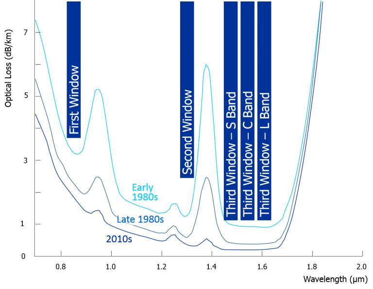
This graph shows how typical single mode fiber attenuation varies with wavelength.
Modern fibers may have a negligible water absorption peak at 1.38 µ
This clearly shows that wavelength uncertainly of tests above 1600 nm has a major impact on loss measurement
