10E: Bi-directional Attenuation
Using Two Sources & Meters, or Two Simple LTS


 Introduction
This method is convenient and accurate for any link. It makes very little difference if a source and meter, or an integrated LTS (Loss Test Set) is used.
Method
The actual method of operation is the same as Example 1, except that:
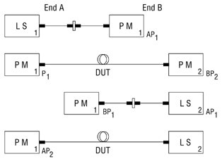
- A source and meter is required at both ends, and the measurement is performed in both directions
- Each source is referenced to the meter at the same end, which should be done just before the measurement. This greatly reduces the problem of source drift, battery life, etc that arise in example 1. The loss results are then noted and manually averaged between the two directions, which cancels out meter (calibration) offsets.
For example AP1, AP2 are the readings from one meter, and BP1, BP2 are the readings from the other.
Averaged link insertion loss in linear units = (AP1+BP1-AP2-BP2)/2 where all measurements are in linear units
[If you use meters with a reference facility, the calculation becomes:
Averaged link loss in linear units = (link loss measured by meter A + link loss measured by meter B)/2 ]
Note that use of this technique eliminates calibration accuracy as an issue, leaving only meter linearity and short term source stability as instrument limiting factors.
In this situation ‘Autotest’ type features can result in better measurement confidence, lower skill requirements and twice the productivity for dual wavelength measurements.
Key
 |
Connectorised link |
 |
Patch Cord |
 |
Through adaptor |
 |
Source, incl. mandrel wrap if multimode |
 |
Meter |
 |
DUT Device Under Test (system being tested) |
[instructions on use of the relative mode are in italics]